Cart
Cart
|
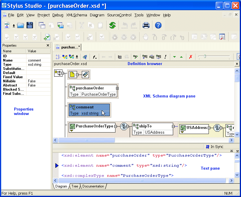
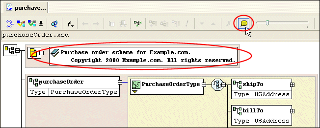
Home >Online Product Documentation >Table of Contents >Introduction to the XML Schema Editor Diagram Tab Introduction to the XML Schema Editor Diagram TabThe recommended way to define an XML Schema in Stylus Studio is to start with the Diagram tab of the XML Schema Editor, which is shown in Figure 50. When you use the Diagram tab to define an XML Schema, you can create XML Schema nodes directly on the XML Schema diagram pane using tools on the tool bar or from the XML Schema > Diagram and shortcut menus. You can also type in the text pane, which appears under the Diagram tab. The text pane displays the XML Schema syntax Stylus Studio creates for you as you work in the diagram pane. Stylus Studio ensures that the XML Schema you create is valid. For example, any nodes you define are created in the required order in the XML document that contains the XML Schema definition, regardless of the order in which you create them. The Diagram tab, shown in Figure 50, consists of three main areas: This section describes these areas and how to work with them. Diagram PaneThe diagram pane contains graphical representations of the elements, attributes, and other nodes that make up your XML Schema. NodesEach node displayed in the diagram pane is represented by its own symbol; tool tips, which are displayed when you hover over a node in the diagram, identify the node's type (element, attribute, sequence, and so on). The symbols used in the diagram are summarized in Table 1.
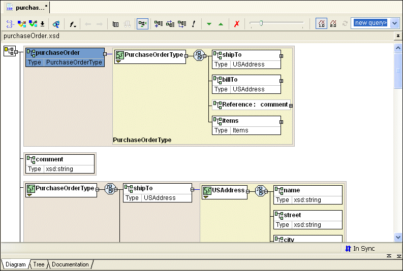
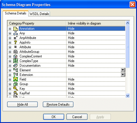
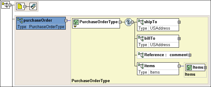
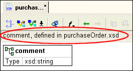
Nodes can be expanded and collapsed using the plus and minus symbols, respectively, that appear on the right side of the node. In Figure 54 for example, the Displaying PropertiesTo streamline the diagram, most nodes are displayed with their properties hidden by default. Exceptions include element, extension, and restriction nodes, for which the type is displayed, as shown in the productName element in Figure 52. You can change the display for classes of nodes (all elements, for example) using the Diagram Properties dialog box, shown in Figure 53. (In addition, the Properties window displays all the properties for any node you select.) For each node property, you can choose to If all of a node's properties have the same show/hide setting, that value is displayed in the Inline Visibility in Diagram field. If no value is displayed in the Inline Visibility in Diagram field, it means that two or more properties have different show/hide settings. To display the Diagram Properties dialog box:
To change node properties display:
1. Display the Diagram Properties dialog box, or the Schema Details page of the Options dialog box.
2. Select the node whose properties display you want to change.
3. Click OK.
Background colorBackground color is used as another visual cue for information about the XML Schema:
Displaying documentation
By default, text associated with documentation elements ( Moving around the diagramThere are several ways to move around the diagram pane:
Text Pane
The text pane appears directly beneath the XML Schema diagram pane. It displays the XML Schema code represented by the nodes you create in the diagram. The default font is Courier New, but you can change it to whatever font you want by clicking the Change Font button (
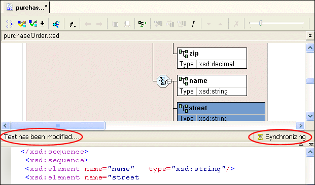
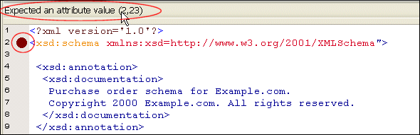
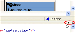
Stylus Studio synchronizes the diagram and text views of the XML Schema - any changes you make in the diagram are reflected in the text pane, and vice versa. Synchronization information is displayed in the bar that separates the diagram and text panes. Current status is displayed on the right. When the two views are synchronized, Stylus Studio displays this graphic: Stylus Studio also flags any XML Schema errors in the text pane - lines that contain errors are identified with a red dot, and the type and location of the error is displayed in the status area at the top of the text pane, as shown here: When you click the error message, Stylus Studio jumps to that part of the XML Schema containing the error. When you correct one error, information about the next error detected by Stylus Studio (if any) is displayed in the status area. You can use the splitter to resize the text pane to view more or less text, or you can hide it entirely using the controls on the splitter's right side. Stylus Studio supports back-mapping between the text pane and the XML Schema diagram pane - if you click a node in the diagram, Stylus Studio scrolls the text pane to display the line of XML Schema that defines the node you clicked. A blue triangle is displayed to the left of the exact line of code. Definition Browser
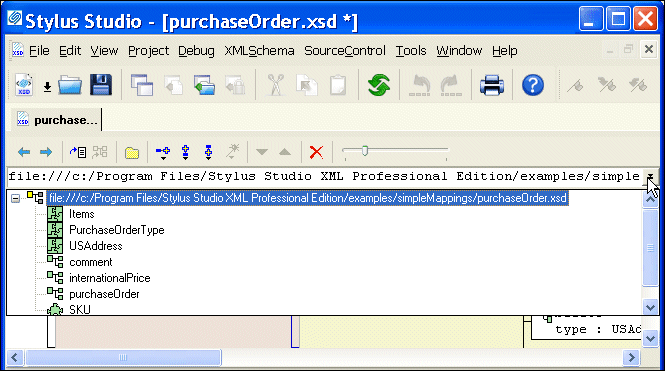
The definition browser is a drop-down list that displays all the child nodes of the When you select a node from the definition browser, Stylus Studio displays a new page in the XML Schema diagram pane that shows the definition of the node you select. In addition, the definition browser displays information about that node.
To return to the page you were viewing previously, press the back ( |
XML PRODUCTIVITY THROUGH INNOVATION ™